Flexure
Eurocode 2 offers various methods for determining the stress-strain relationship of concrete in flexure. For simplicity and familiarity the method presented here is the simplified rectangular stress block (which is similar to that found in BS 8110). In determining the resistance of sections, the following assumptions are made.
- Plane sections remain plane.
- Strain in the bonded reinforcement, whether in tension or compression, is the same as that in the surrounding concrete.
- Tensile strength of the concrete is ignored.
- Stress distribution in the section is as shown in Figure 2 - simplified rectangular stress block
- Stresses in reinforcement are derived from Figure 6.2
Figure 2: Simplified rectangular stress block for concrete up to class C50/60 from Eurocode 2
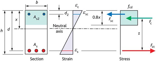
Extract From How to Design Concrete Structures using Eurocode 2 (page 64, Figure 2)
Figure 6.2: Idealised and design stress-strain diagrams for reinforcing steel (for tension and compression)
Extract from Concise Eurocode 2 (page 37, figure 6.2) (The inclined branch of the design line may be used when strain limits are checked.)
Proof: singly reinforced beams and slabs
The majority of beams and slabs used in practice are singly reinforced. Design equations for the amount of reinforcement required can be derived as follows (refer to Figure 2 above):
Fc = (0.85 fck / 1.5) b (0.8 x) = 0.453 fck b x
Fst = 0.87As fyk
Take moments about the centre of the tension force
M = 0.453 fck b x z . . . . . . . (1)
Now z = d - 0.4 x
\ x = 2.5(d - z)
& M = 0.453 fck b 2.5(d - z) z
= 1.1333 (fck b z d - fck b z2)
Let K = M / (fck b d 2)
\ 0 = 1.1333 [(z/d)2 – (z/d)] + K
0 = (z/d)2 – (z/d) + 0.88235K
Solving the quadratic equation:
z/d = [1 + (1 - 3.529K)0.5]/2
z = d [1 + (1 - 3.529K)0.5]/2
So the lever arm for an applied moment is known
Take moments about the centre of the compression force
M = 0.87As fyk z
Rearranging
As = M /(0.87 fyk z)
The required area of reinforcement can now be calculated. For convenience for hand calculations, tables of values of z/d according to K are published, for instance in Concise Eurocode 2 and in How to Design Concrete Structures using Eurocode 2, page 33, Table 5.
Limiting neutral axis depth
As a beam experiences more moment, it is often considered good practice to limit the depth of the neutral axis to avoid ‘over-reinforcement’ (i.e. to ensure that the reinforcement has passed its yield point). This is not a Eurocode 2 requirement and is not accepted by all engineers. A limiting value for K can be calculated (denoted K’) as follows.
ecu3 = 0.0035 = Concrete strain (from EN1992-1-1 Table 3.1)
es = 500 / (1.15 x 200 x 103) = 0.0022 = reinforcement strain
From strain diagram:
x = 0.0035 d /(0.0035 + 0.0022)
= 0.6 d
From Eqn 1 above:
M = 0.453 fck b x z
M’ = 0.453 fck b 0.6 d (d – 0.4 x 0.6 d)
= 0.207 fck b d2
\ K’ = 0.207
Beyond K’ compression reinforcement is required. Neutral axis depth x varies with the amount of redistribution of moments. K’ = 0.207 is valid where there is no redistribution but for redistributions of 15%, K’ = 0.168 is appropriate. In the UK it is often recommended that K’ should be limited to 0.168 to ensure ductile failure.
Proof: compression reinforcement
In some cases, compression reinforcement is added to increase section strength where section dimensions are restricted i.e. where K > K’. It may also be added to reduce long term deflection or to decrease curvature/deformation at ultimate limit state. It may also be added to reduce long term deflection or to decrease curvature/deformation at ultimate limit state.
With respect to Figure 1, we now need to consider an extra force Fsc = 0.87As2 fyk
The area of tension reinforcement can now be considered in two parts, the first part to balance the compressive force in the concrete, the second part is to balance the force in the compression steel. The area of reinforcement required is therefore:
As = K’ fcu b d 2 /(0.87 fyk z) + As2
where z is calculated using K’ instead of K
As2 can be calculated by taking moments about the centre of the tension force:
M = K’ fcu b d 2 + 0.87 fyk As2 (d - d2)
Rearranging
As2 = (K - K’) fcu b d 2 / (0.87 fyk (d - d2))
High strength concretes
Eurocode 2 gives recommendations for the design of concrete up to class C90/105. However, for concrete greater than class C50/60, the concrete compression stress block is modified (See EN 1992-1-1 Cl. 3.1.7(3).