Strut and tie
Strut and tie modelling (STM) is a simple method which effectively expresses complex stress patterns as triangulated models. STM is based on truss analogy and can be applied to many elements of concrete structures. It is usually adopted to design non-standard elements or parts of elements of concrete structures such as pile caps, corbels, deep beams (where depth > span/3), beams with holes, connections, etc. where normal beam theory does not necessarily apply.
STM is a powerful engineering tool where the engineer stays in control. With a reasonable amount of experience, it can help design engineers provide simple engineering solutions to complex structural problems.
Possibly due to the lack of previous applicable design standards, STM was not popular in the UK and its use was generally limited. However, Eurocode 2 now includes STM, allowing and perhaps encouraging its more widespread use. Even so, there is little simple guidance within Eurocode 2 or indeed elsewhere. The intention of The Concrete Centre publication, Strut-and-Tie Models is therefore to give guidance and impart understanding of the method.
STM is a lower bound plastic theory which means it is safe providing that:
- Equilibrium is satisfied.
- The structure has adequate ductility for the assumed struts and ties to develop.
- Struts and ties are proportioned to resist their design forces.
The design process for strut-and-tie models can be summarised into four main stages:
- Define and isolate B- and D- regions (i.e. beam or Bernoulli and disturbed or discontinuity regions).
- Develop a STM - a truss system to represent the stress flow through the D-region and calculate the member forces in the truss.
- Design the members of the STM - dimension and design the truss members to resist the design forces.
- Iterate to optimise the STM as necessary to minimise strain energy.
These four steps are explained in the first four sections of The Concrete Centre guidance Strut-and-Tie Models.
A very simple example for the strut-and-tie design of a two-pile cap is shown below.
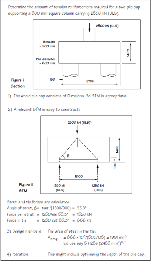
Extract from Strut and Tie Models, page 3.
A For clarity, the self-weight of the pile cap assumed to be included.
B Although not usually critical for pile caps in a structural grade of concrete, in a full final design the stresses around the nodes and the capacity of the struts should be checked.
C Some attention should also be given to reinforcement details, particularly anchorage which, when using strut and tie, is different to that using beam theory.